Senior Design Project Overview
For my senior design project, I collaborated with three other mechanical engineers to design and build a mount for holding the Design/Build/Fly plane on a car. By driving at the plane's typical flight speed, we simulated flight conditions and collected data on lift, drag, and torque using Adafruit strain gauge load cell sensors connected to load cell amplifiers, an Arduino Uno, and a laptop for data recording. Code was used to calibrate the load cell sensors and export the collected data from the Arduino IDE to Excel for data analysis. The experimental data collected by the plane mount was compared with simulated results from XFLR5 and Ansys to see how greatly the experimental drag and lift coefficient values differ from their theoretical values.
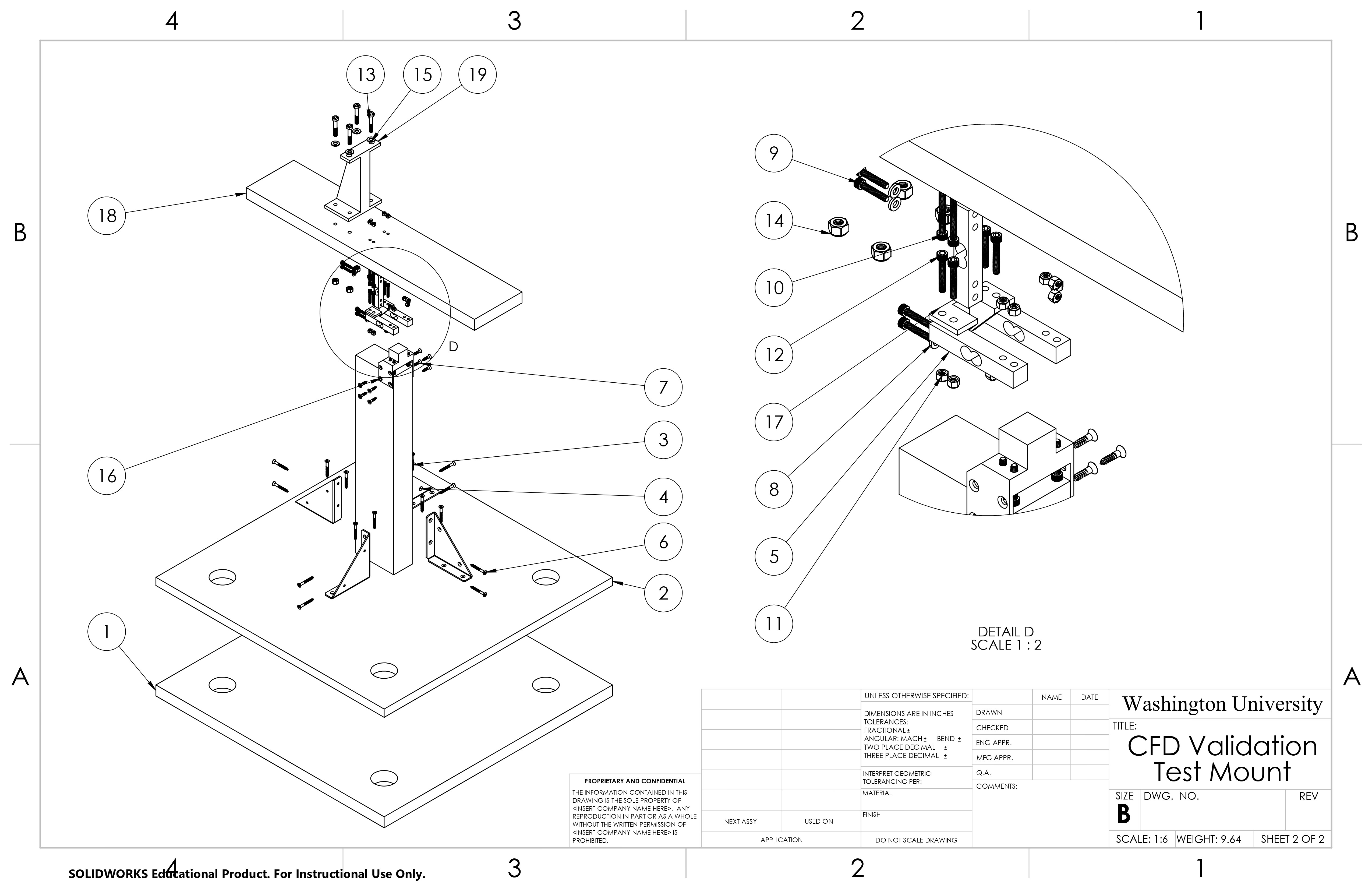
SolidWorks Drawings
Below are SolidWorks CAD drawings for our senior design project showcase the detailed design of the RC plane mount, including multiple configurations, an exploded view, and component-specific illustrations. These visuals provide a comprehensive overview of the device, along with a Bill of Materials (BOM) to outline all parts and materials used in the build.


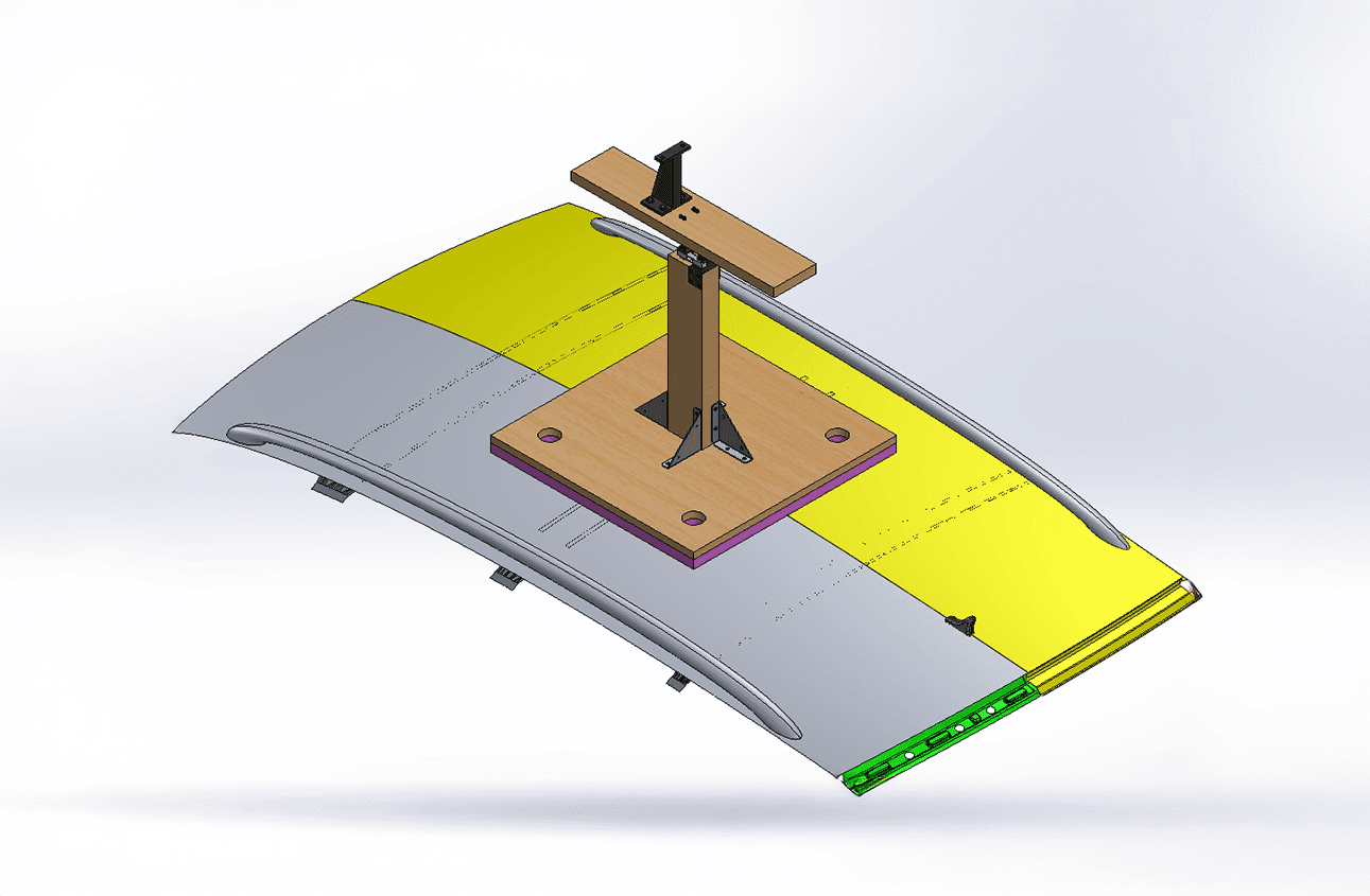
Isometric View
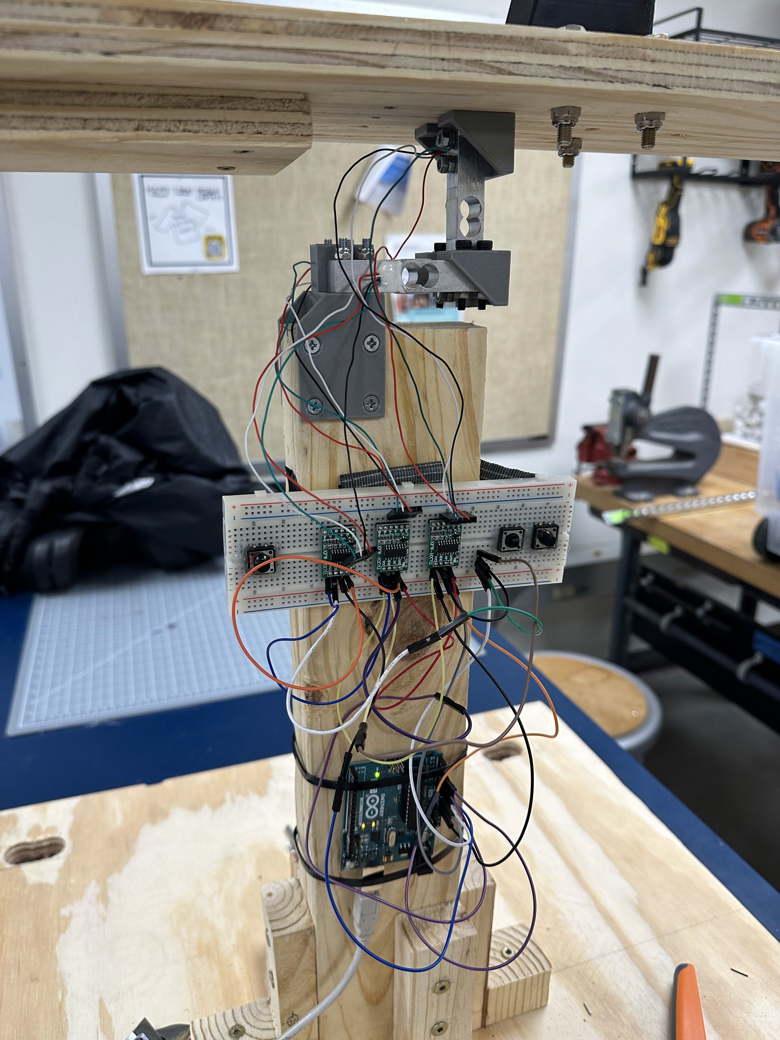
Strain Gauge Sensors to Load Cell Amplifiers to Arduino Uno
For my senior design project, I implemented a data acquisition system using Adafruit strain gauge load cells connected to load cell amplifiers, which in turn were connected to an Arduino Uno and a laptop. This setup enabled precise measurement and recording of lift, drag, and torque (left and right) as the plane was mounted on a moving vehicle. By simulating real flight conditions, this system allowed us to capture accurate air-load data for validation against computational models.

Code was written to calibrate each of the load cells, collect numerical values, and export the data to Excel for analysis. The live data feed from the Arduino IDE allowed us to see the force values each load cell was experiencing in real time. Each load cell was wired to the same clock pin but had its own data pin. That way, 1 uniform time value was used during data analysis instead of a unique time value for each load cell. Our code is below in a .ino file written in the Arduino IDE. The Arduino IDE uses Arduino C/C++ which is a simplified version of C++ tailored for programming Arduino microcontrollers.
Close Up of the Mount
The load cells are oriented to support the plane to record lift and drag data accurately. The plane is attached to the mount using 2 bolts and nuts that fasten the plane's fuselage to the mount. The plane's fuselage was selected as the mounting point because it is the strongest section of the plane.


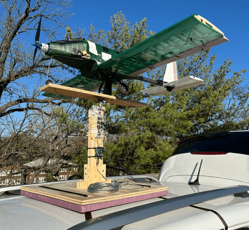
Full Mount on a Car
Video of the Mount in Action
GoPro Footage
Raw Data
The graphs below show the drag and lift data collected while driving at 30 mph. The region between the 2 black lines in both graphs shows the data once the car had reached a steady speed of 30 mph.
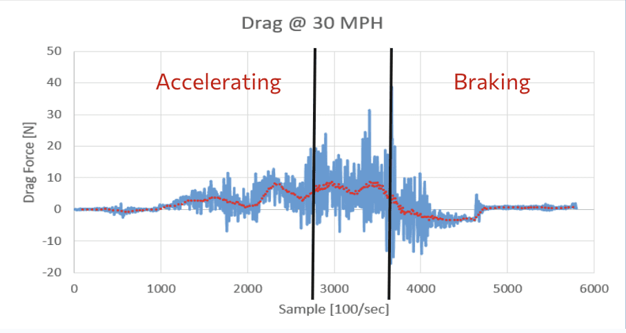

The drag force at a steady speed of 30 mph was roughly 6.5 N and the lift force was roughly 15 N. These values were calculated using a moving average of 100 points in the steady 30 mph region.
Results Table
The table below shows the drag and lift coefficient results while driving at 30 mph compared with the theoretical XFLR5 and Ansys values.

While our results were at least similar in magnitude, uneven roads and vibrations played a major role in adding noise and inaccuracies to our data. Future next steps are finding ways to decrease vibrations from the car and plane mount to improve the similarity of the experimental plane mount data and the simulated theoretical data.