The objective of this research was to create a universal robotic end effector also known as a jamming gripper and test the effectiveness of coffee grounds vs. kinetic sand as the granular material used in the end effector. The apparatus used was a system containing an Arduino UNO, a 12-volt vacuum pump, an h-bridge, a solenoid valve, and the jamming gripper itself. An assortment of objects was used to see how well the gripper could pick up objects of different sizes, shapes, and weights. After various trials, the coffee grounds yielded much better results than the kinetic sand. The kinetic sand adhered too strongly to itself and lacked the soft-to-hard phase transition that the coffee grounds possess. This phase transition allows the coffee grounds to conform to an object and grip onto it when necessary while also separating adequately when the object needs to be released. The eventual goal is to create a fully autonomous universal robotic end effector and collaborative robot system that can pick up and place delicate and uniquely shaped objects.
Demonstration Video
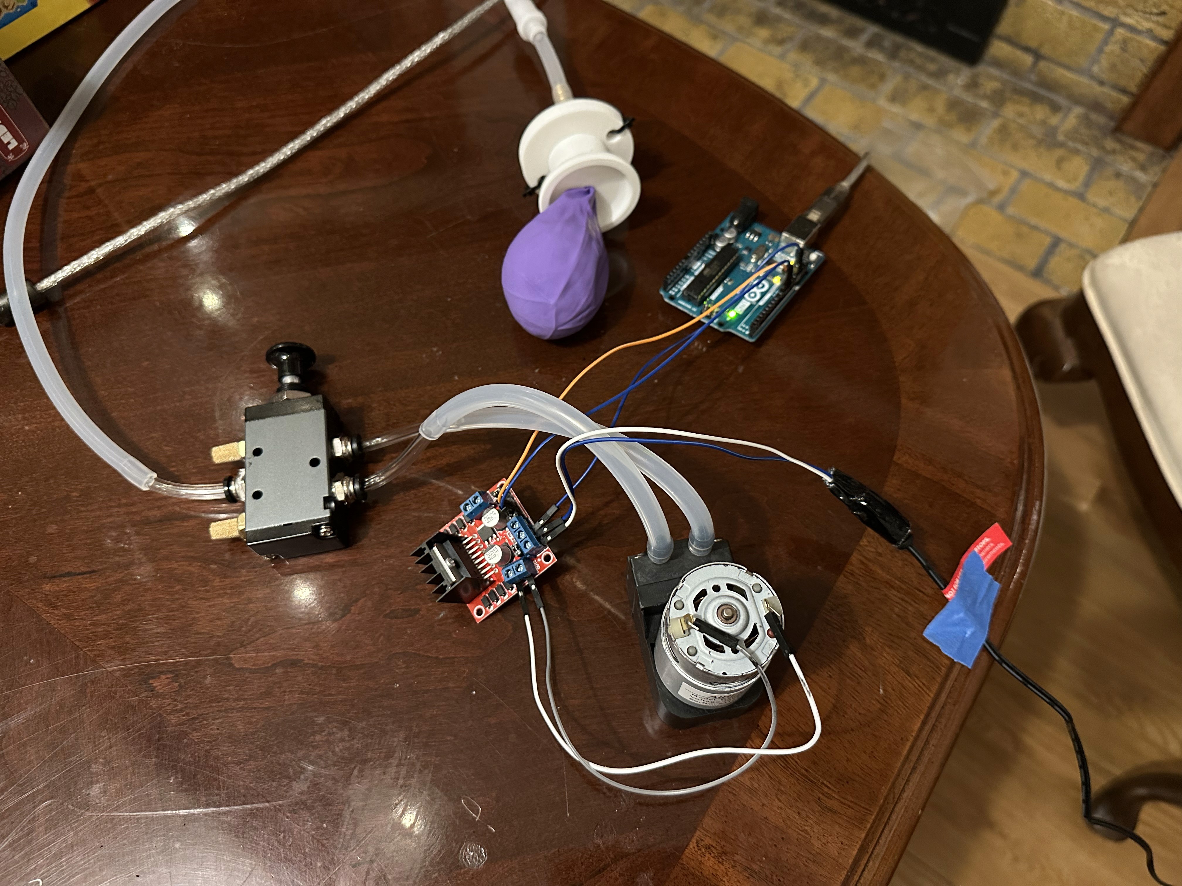
The jamming gripper is designed to conform to and lift objects of various shapes using vacuum pressure and coffee grounds. By removing air from a balloon filled with granular material, the gripper stiffens around an object, securely lifting it before returning to a soft state to release by inflating the balloon. In this demo, you’ll see how the system works in real time using an Arduino-controlled vacuum setup.
Results of the Coffee Grounds vs. Kinetic Sand Comparison
Testing revealed that coffee grounds significantly outperformed kinetic sand as the granular material for the jamming gripper. While coffee grounds conformed well to objects and enabled reliable gripping through a soft-to-rigid phase transition, kinetic sand clumped together and failed to adapt to object shapes, making it ineffective for gripping tasks.
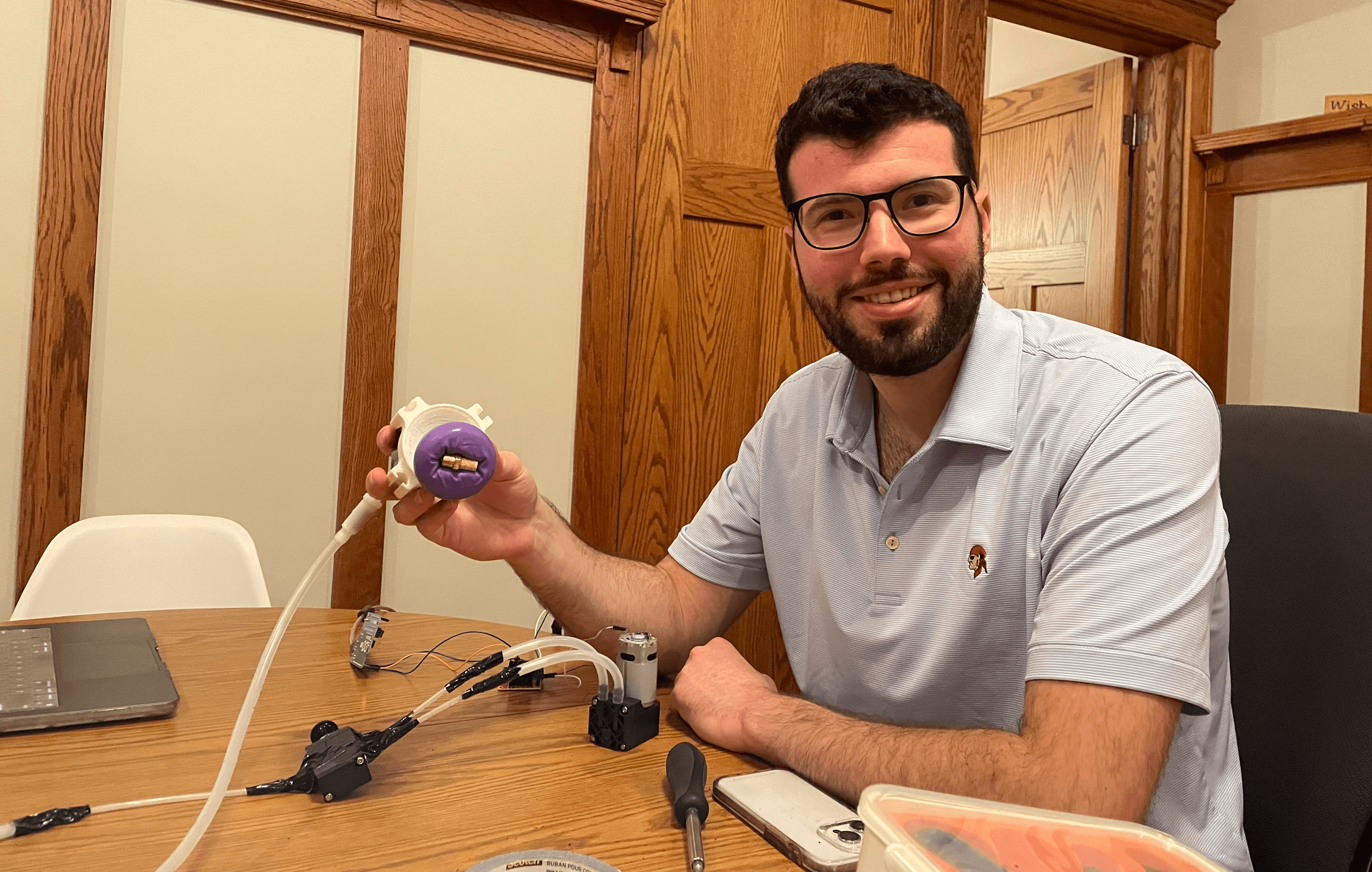
Me with the Gripper
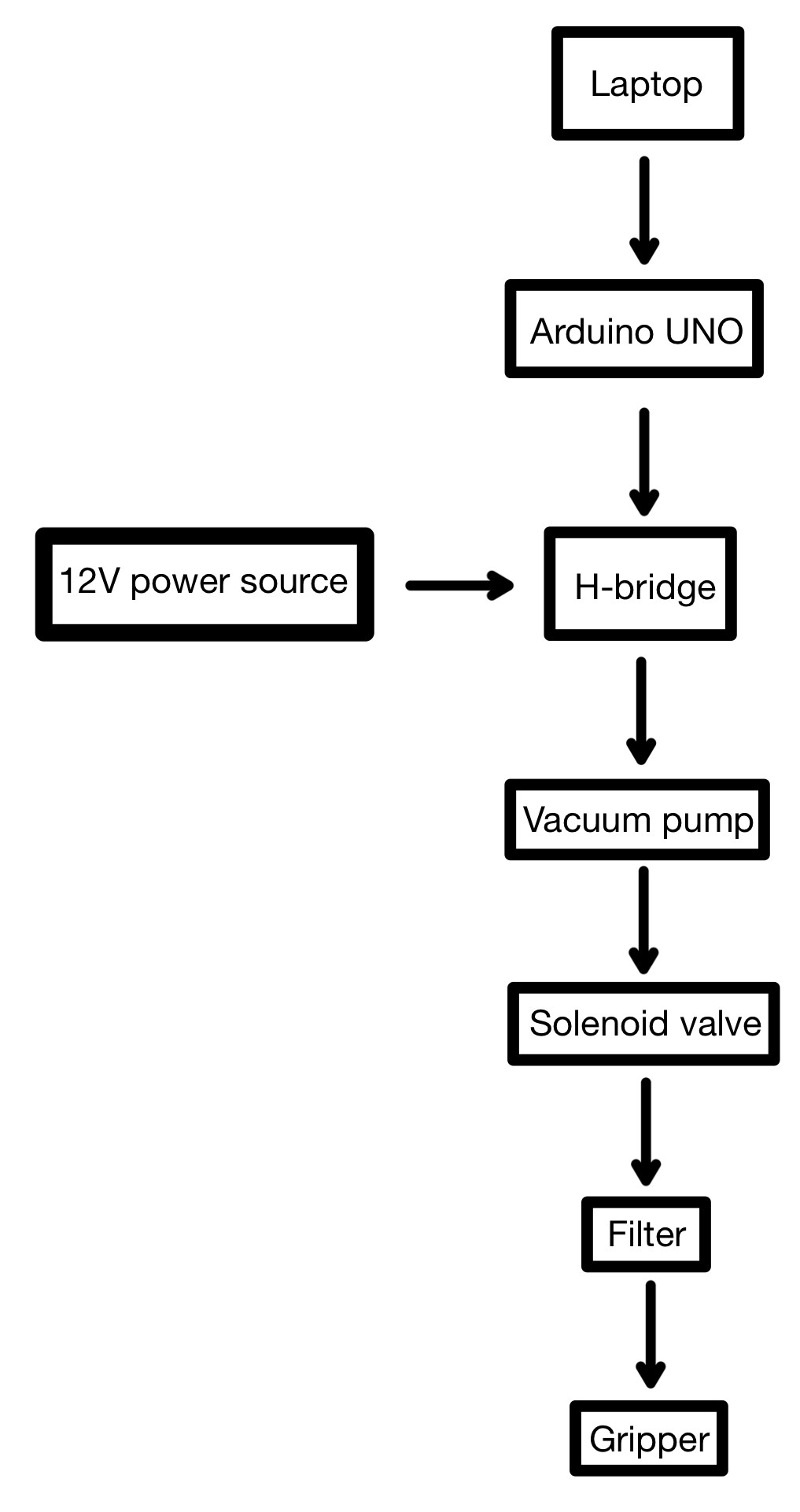
Setup and Procedure Diagram
This procedure diagram outlines the flow of the jamming gripper system. A laptop powers and controls the Arduino UNO, which sends signals to an H-bridge powered by a 12V source. The H-bridge activates the vacuum pump, which draws air through a solenoid valve. Airflow then passes through an inline filter, preventing granular material from entering the pump, before reaching the gripper, where vacuum pressure causes the coffee grounds inside a latex balloon to conform around and grip an object.
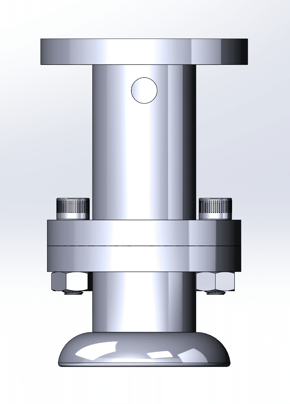
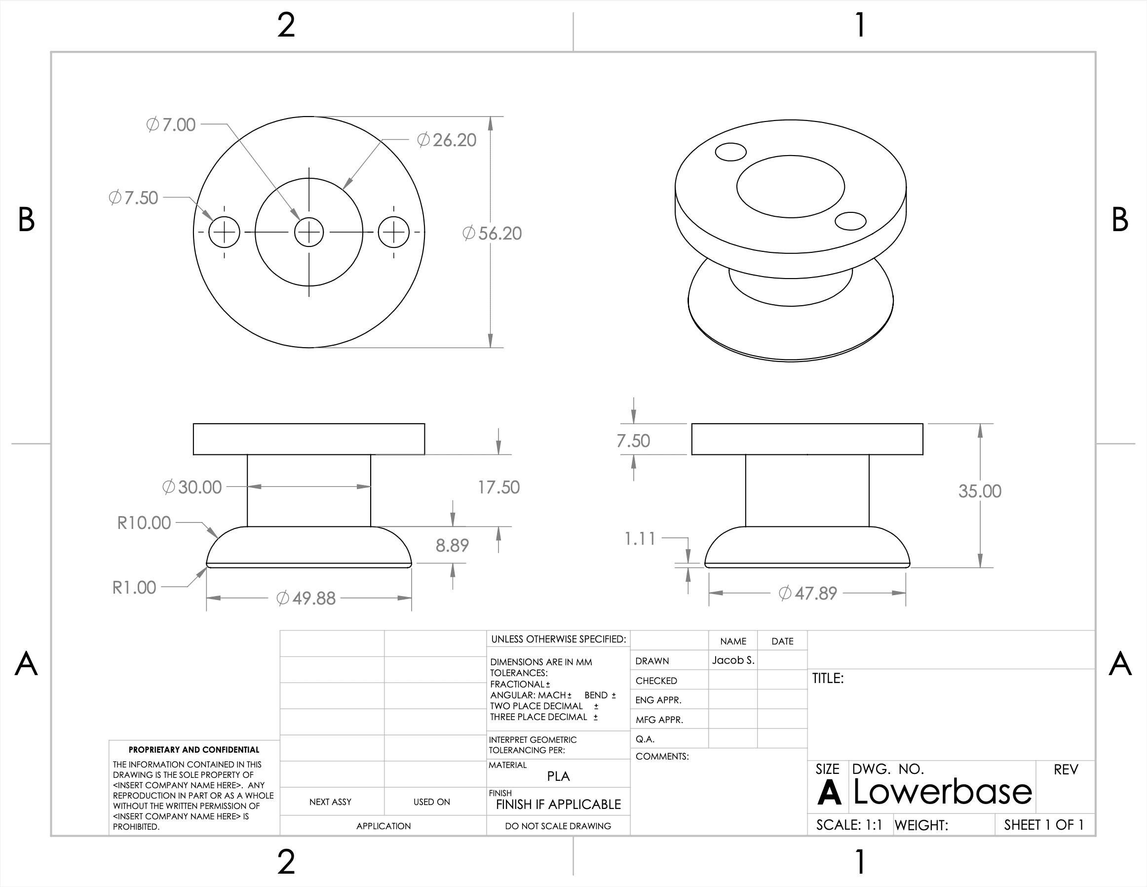
3D-Printed Gripper Casing Design
The 3D-printed gripper casing was designed to support and guide the latex balloon during inflation and deflation, helping it conform properly to objects. Its bowl-shaped interior contains the balloon, while a central cylindrical grip and holes for zip ties allow for easy handling and secure attachment to other components. A hole in the center accommodates the tubing and inline filter, allowing airflow while preventing granular material from entering the vacuum system.
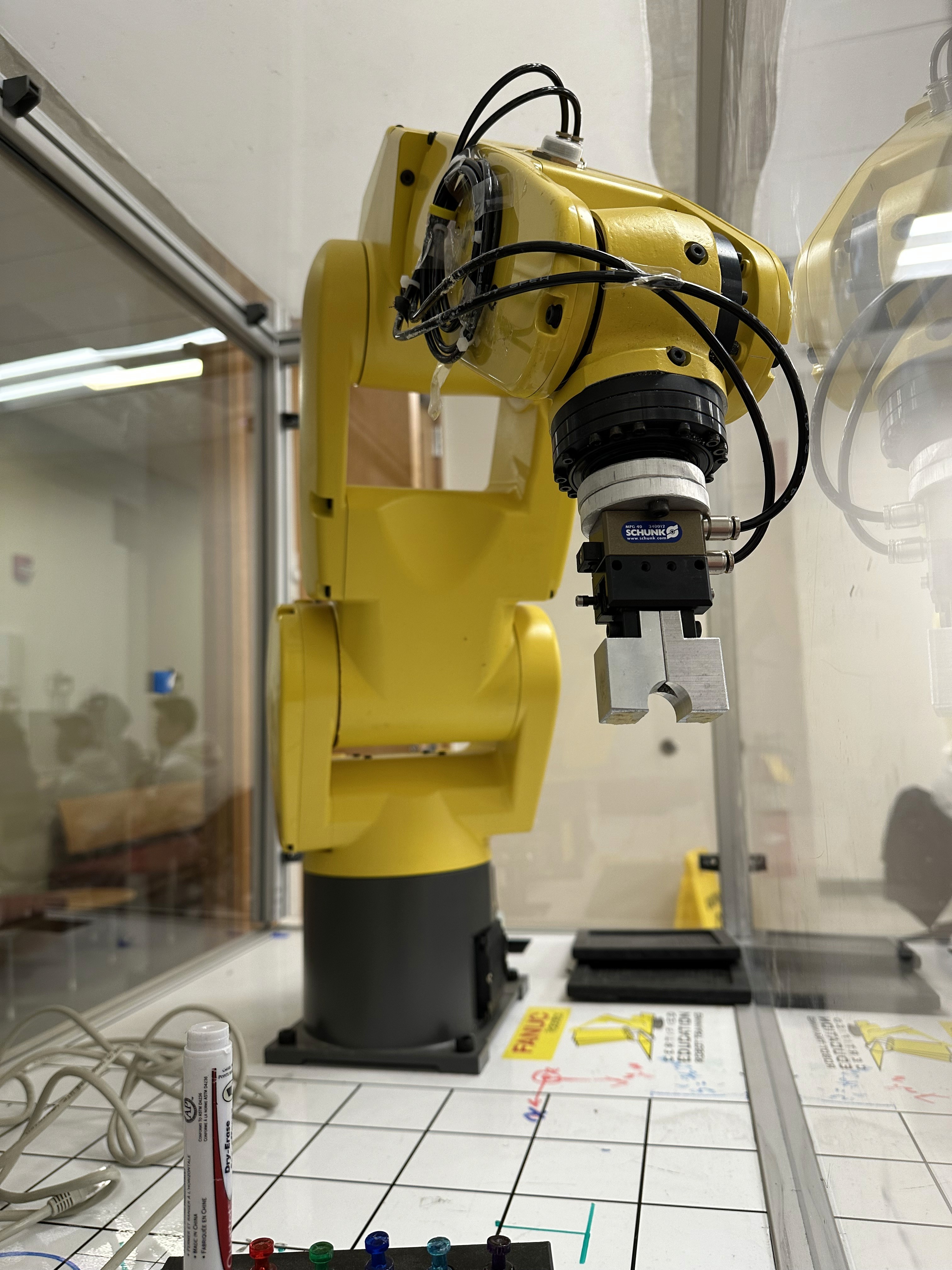
Future Steps for Full FANUC Cobot Integration
For future integration with the FANUC collaborative robot (cobot), several key steps are planned to create a fully autonomous end-effector system:
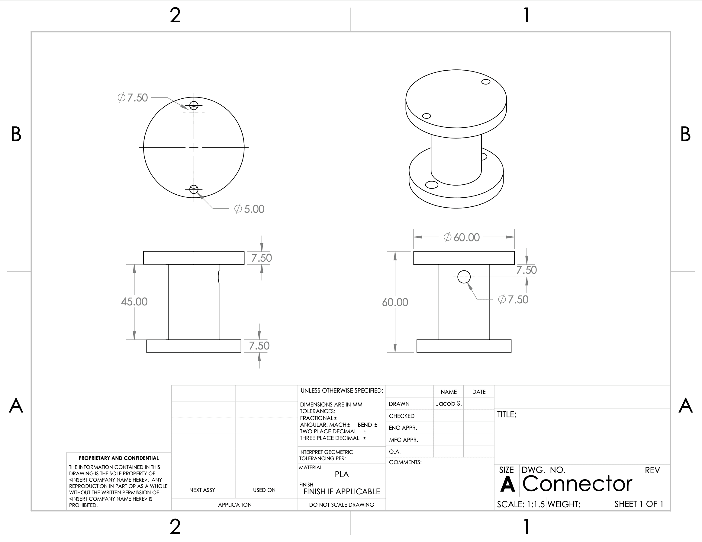
Mechanical Mounting: A 3D-printed connector was designed to securely attach the gripper casing to the FANUC cobot’s wrist using hex screws. This ensures stable interfacing and accurate alignment during operation.
Automated Valve Control: Currently, a manual lever switches the solenoid valve between inflation and deflation. Replacing this with a servo motor controlled by the Arduino would automate the pressure change process.
Pressure Sensing: Adding a pressure sensor inside the balloon would allow real-time monitoring of internal pressure, enabling the system to switch modes at optimal times without human input. This improves consistency and responsiveness.
Programming the Cobot: Once the gripper is mechanically and electrically integrated, the FANUC arm will be programmed to coordinate movements with inflation/deflation timing. This includes controlling pickup, placement, and optimal approach angles for various objects.
System Consolidation: Reducing wiring, combining power sources, and improving component layout will help make the system more compact and reliable for robotic use.
Computer Vision Integration (Future Step): Incorporating cameras and object detection could allow the robot to assess object size, shape, and orientation—adjusting gripper timing and approach for optimal performance.
These steps aim to turn the current prototype into a robust, plug-and-play tool for delicate and adaptive object manipulation in collaborative robotic environments. Below are photos of WashU's FANUC robot on campus and a CAD files of a 3D printed connector that will attach the 3D printed gripper casing to the cobot.