Mindstorms EV3 AGV Robot With Gripper

Mindstorms EV3 AGV Robot With Gripper Overview

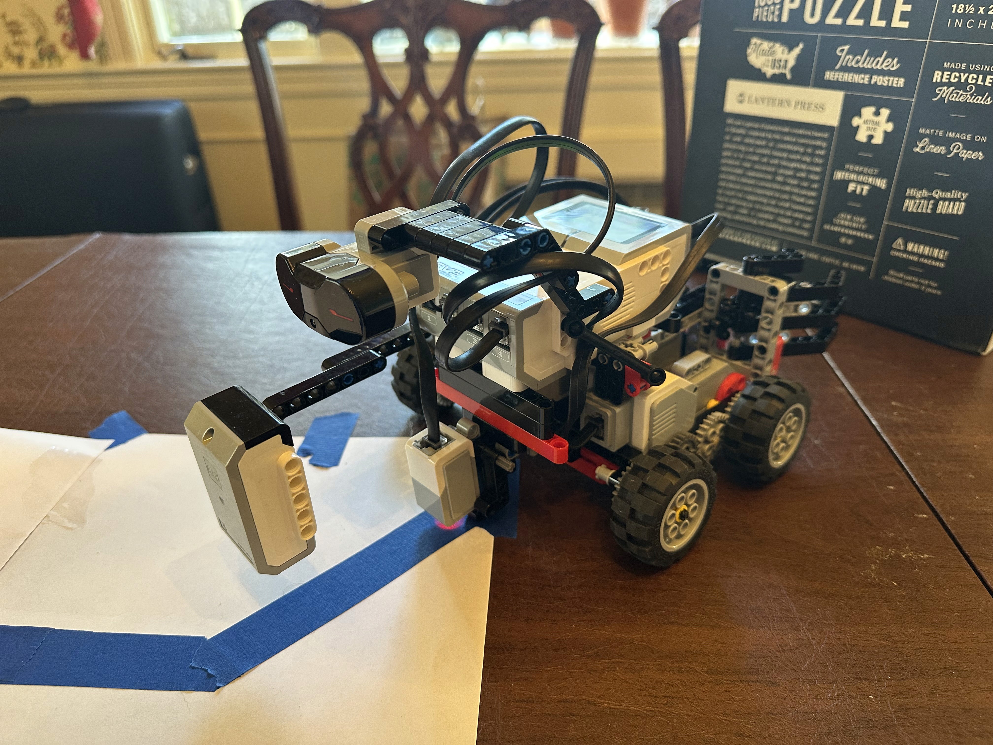
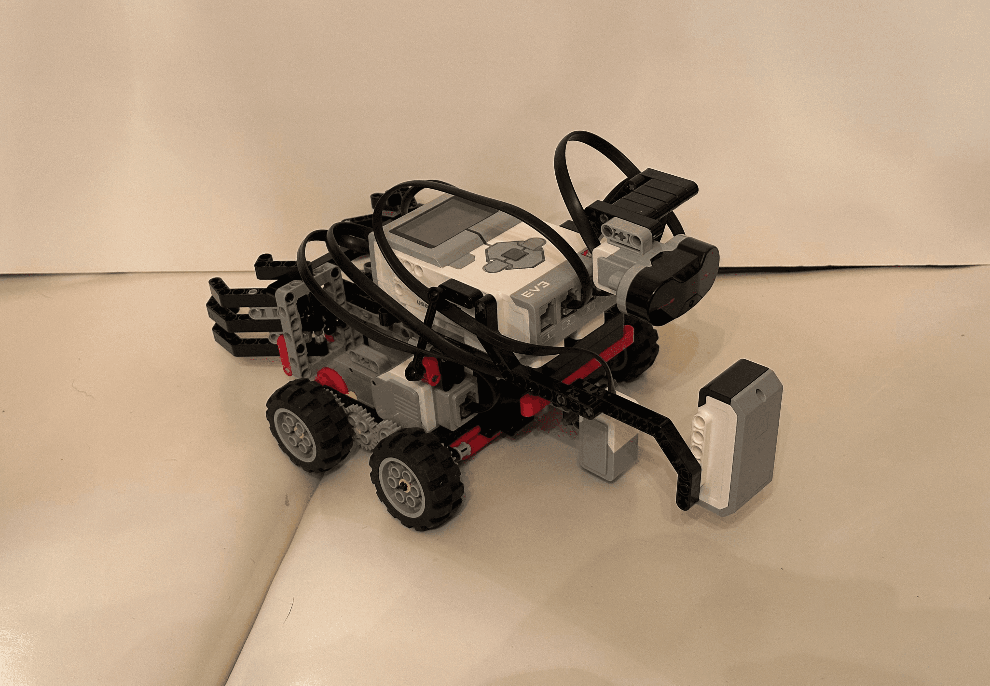
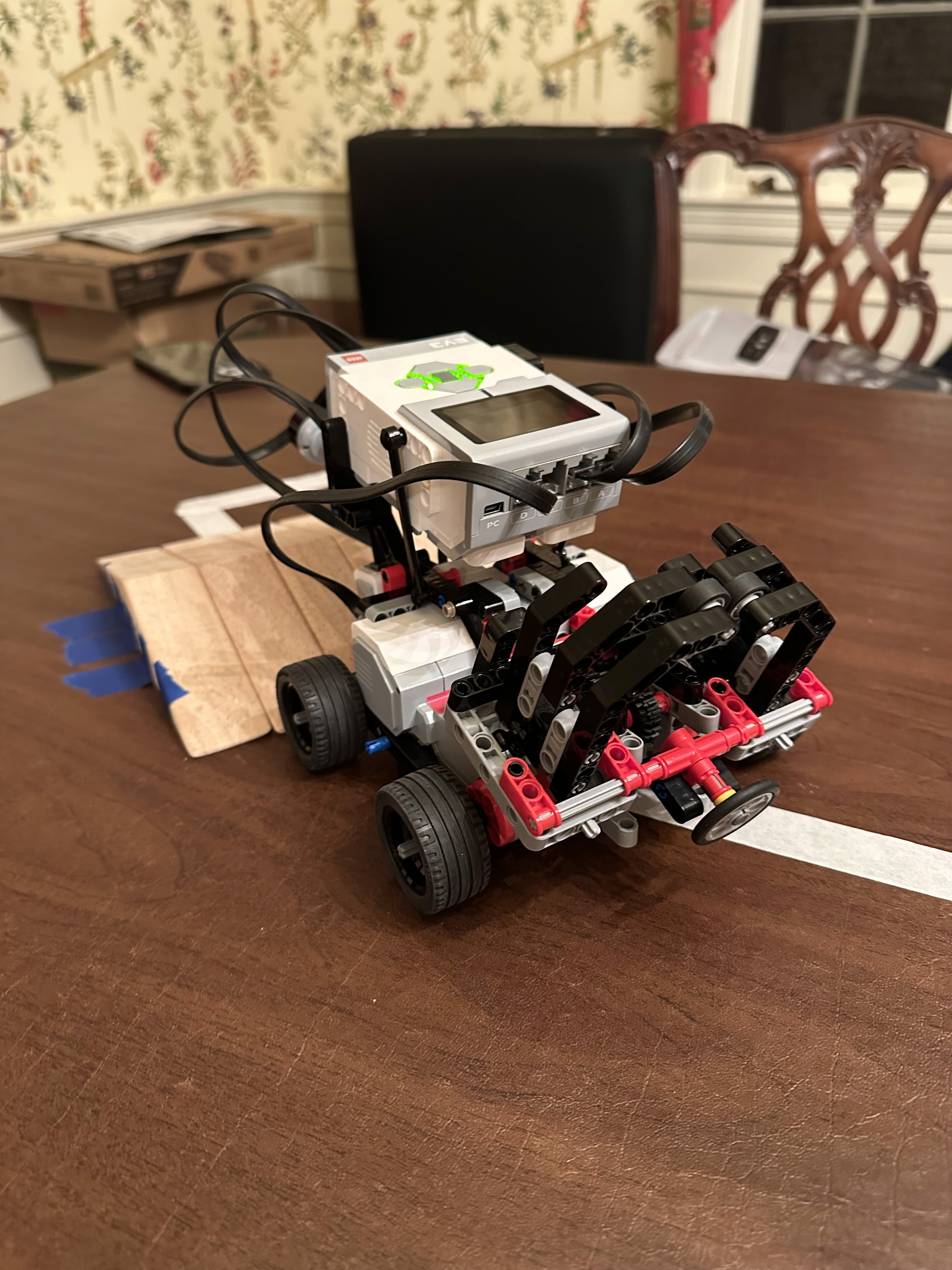
This robot was designed and programmed to follow a line autonomously, grab an object upon detection, and carry the object back to the starting point. I programmed the robot to perform these tasks using Python and LabVIEW to gain experience using both languages. The robot uses 3 motors: one on the left, one on the right, and a motor for the gripper. It also has a color sensor, infrared sensor, and touch sensor.

Python Version: Video and Code

Below is the Python code used in the video above.

#!/usr/bin/env pybricks-micropython
from pybricks.hubs import EV3Brick
from pybricks.ev3devices import (Motor, TouchSensor, ColorSensor,
                                 InfraredSensor, UltrasonicSensor, GyroSensor)
from pybricks.parameters import Port, Stop, Direction, Button, Color
from pybricks.tools import wait, StopWatch, DataLog
from pybricks.robotics import DriveBase
from pybricks.media.ev3dev import SoundFile, ImageFile

# EV3 brick object
ev3 = EV3Brick()

#Initialize left, right, and gripper motors
LM = Motor(Port.D, Direction.CLOCKWISE, [8,24,24,24,8,24])
RM = Motor(Port.A, Direction.CLOCKWISE, [8,24,24,24,8,24])
GM = Motor(Port.B, Direction.CLOCKWISE)

#Initialize color sensor, infrared sensor, and touch sensor
CS = ColorSensor(Port.S2)
IF = InfraredSensor(Port.S4)
TS = TouchSensor(Port.S3)

#Lego wheel and tire total diameter in mm
wheel_diameter = 45

#Distance between where the wheels touch the ground in mm
axle_track = 160

# Initialize the drive base.
robot = DriveBase(LM, RM, wheel_diameter, axle_track)

#Program here
ev3.speaker.beep()

#See initial sensor outputs
print(TS.pressed())
print(IF.distance())
print(CS.color())

#Open gripper claw
while TS.pressed() != True:
    GM.run(-300)

# Calculate the light threshold. Blue and white values are found from
# light sensor testing
BLUE = 5
WHITE = 63
threshold = (BLUE + WHITE) / 2.1

#Set drive speed
DRIVE_SPEED = 80

# Set the gain of the proportional line controller. For every
# percentage point of light deviating from the threshold, set the turn
# rate of the drivebase to 1.2 degrees per second

# If the light value deviates from the threshold by 10, the robot
# steers at 10*1.2 = 12 degrees per second
PROPORTIONAL_GAIN = 1.2

# Start following the line until the stack is within infrared sensor range
while IF.distance() > 50:
    # Calculate the deviation from the threshold
    deviation = CS.reflection() - threshold

    # Calculate the turn rate
    turn_rate = PROPORTIONAL_GAIN * deviation

    # Set the drive base speed and turn rate
    robot.drive(DRIVE_SPEED, turn_rate)
    print(IF.distance())

    wait(30)

#Backup
robot.straight(-40)

#Turn around
robot.turn(170)

#Drive gripper into tire stack
robot.straight(-110)

#Grab tire stack
GM.run_angle(speed=300, rotation_angle=600, then=Stop.HOLD, wait=True)

#Adjust robot angle
robot.turn(30)

# Follow the line back to the start
while IF.distance() > 30:
    # Calculate the deviation from the threshold
    deviation = CS.reflection() - threshold

    # Calculate the turn rate
    turn_rate = PROPORTIONAL_GAIN * deviation

    # Set the drive base speed and turn rate
    robot.drive(DRIVE_SPEED, -turn_rate)
    print(IF.distance())

    wait(30)

#Turn around
robot.turn(180)

#Dropoff tire stack
while TS.pressed() != True:
    GM.run(-300)

#Nudge stack to prevent falling
robot.straight(-10)

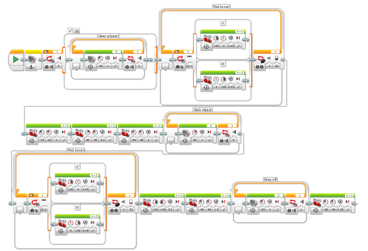
LabVIEW Version: Video and Code

Below is a screenshot of the LabVIEW code used in the video above.

Progression

Initially, the line following the course was short and did not have a ramp as seen in the video below.

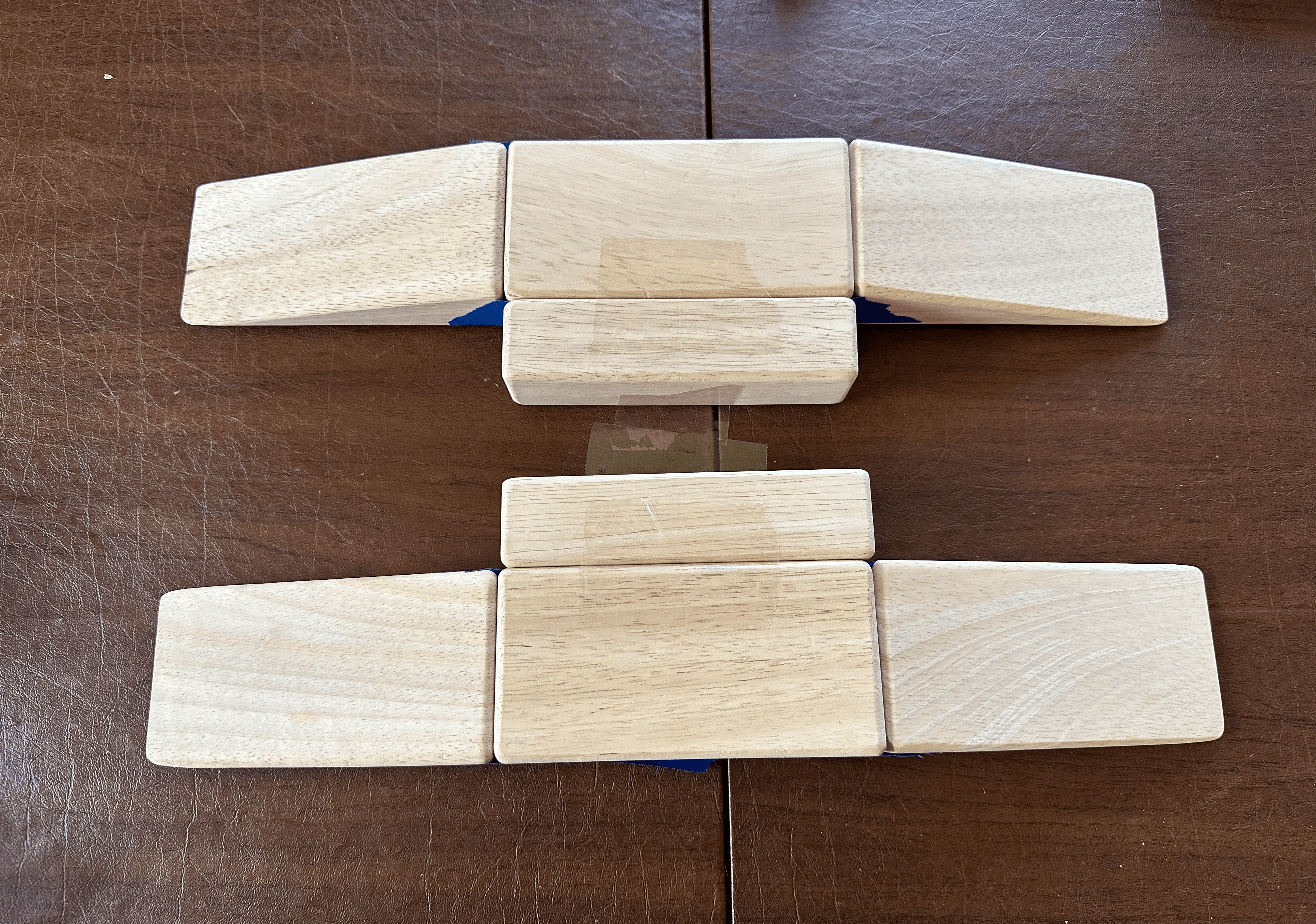
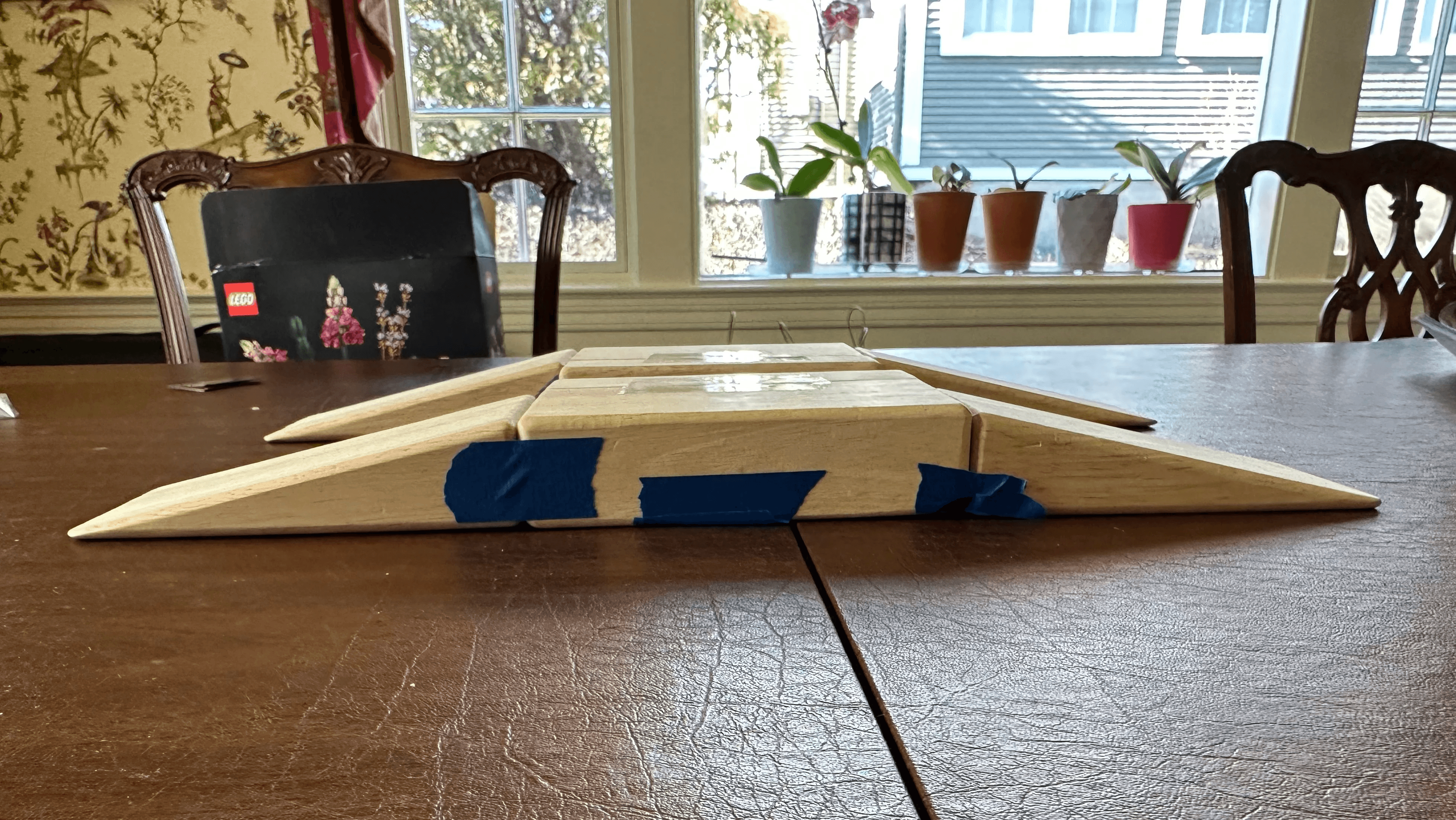
I decided that I wanted to make the challenge harder. I added a ramp made of wooden blocks to add another level of challenge.

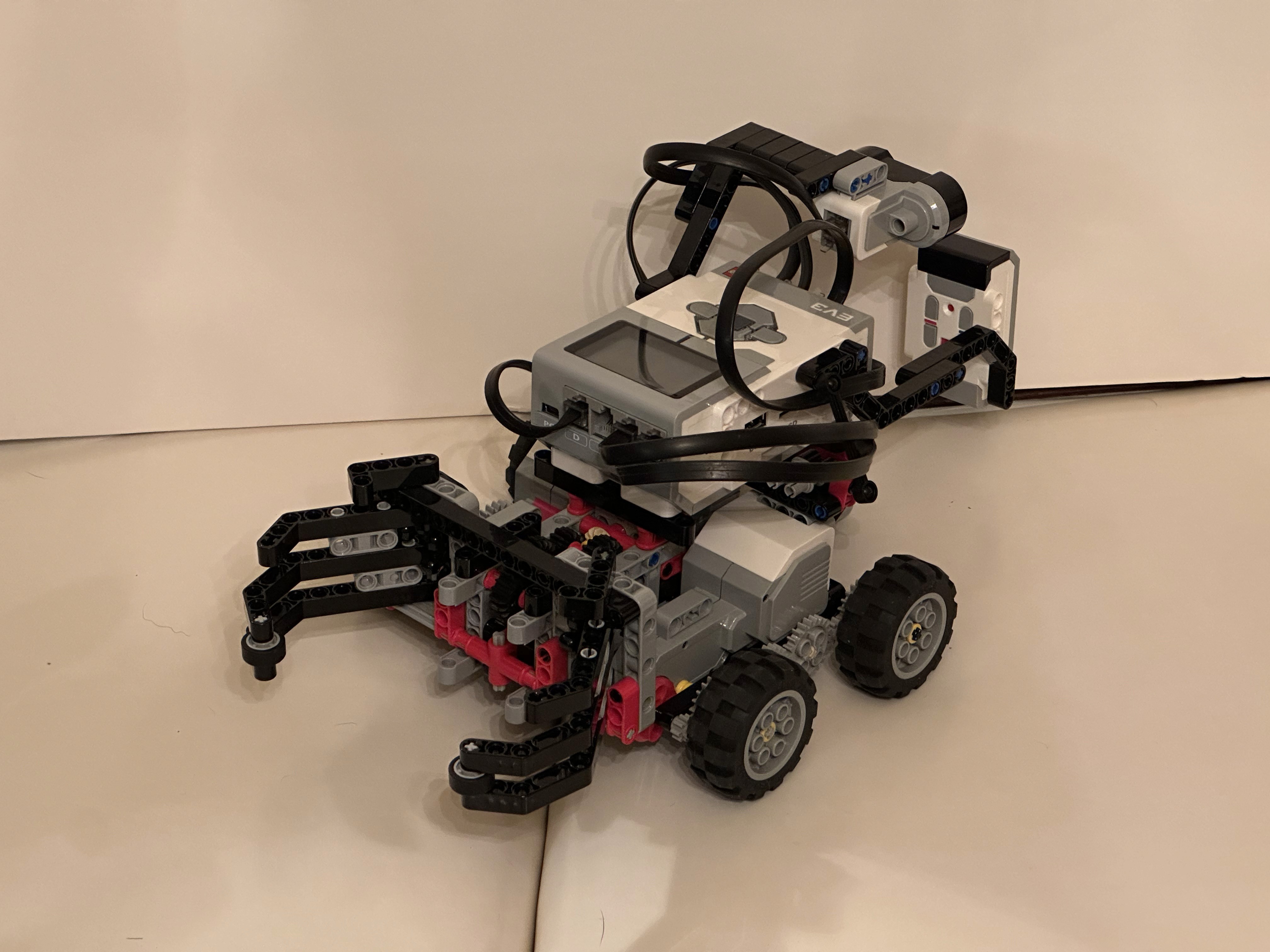
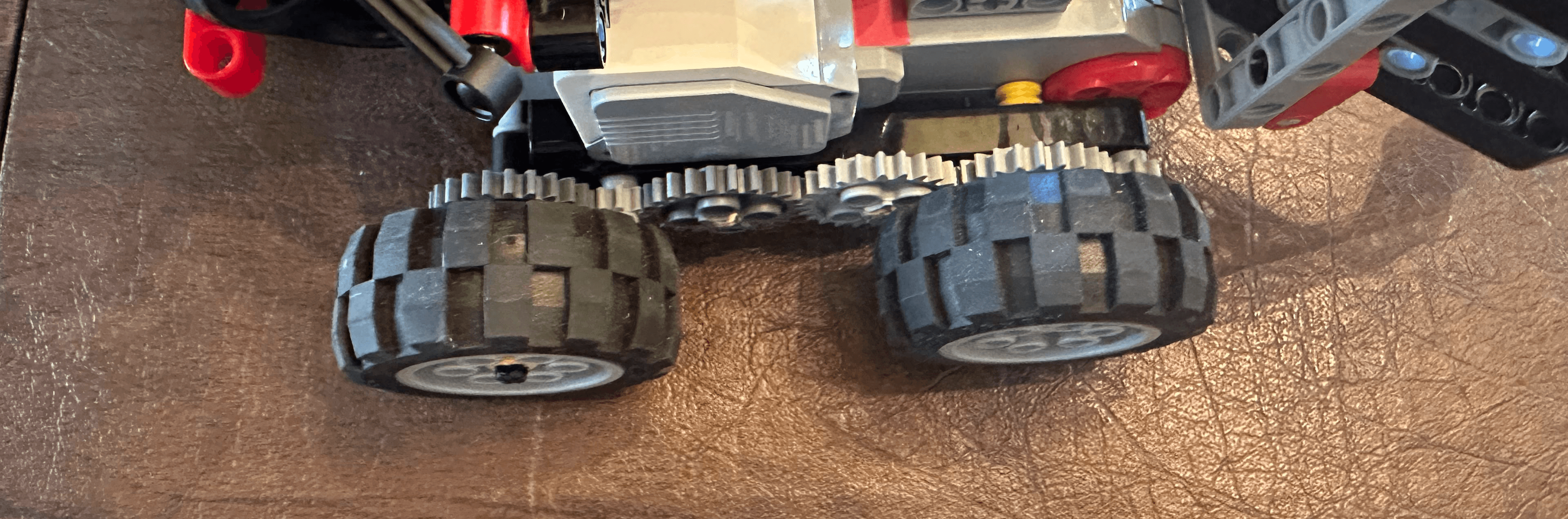
When it came to climbing the ramp, I found that the treads did not have a lot of grip or torque. After testing the treads, smaller wheels, and larger wheels, the larger wheels did the best climbing the ramp.

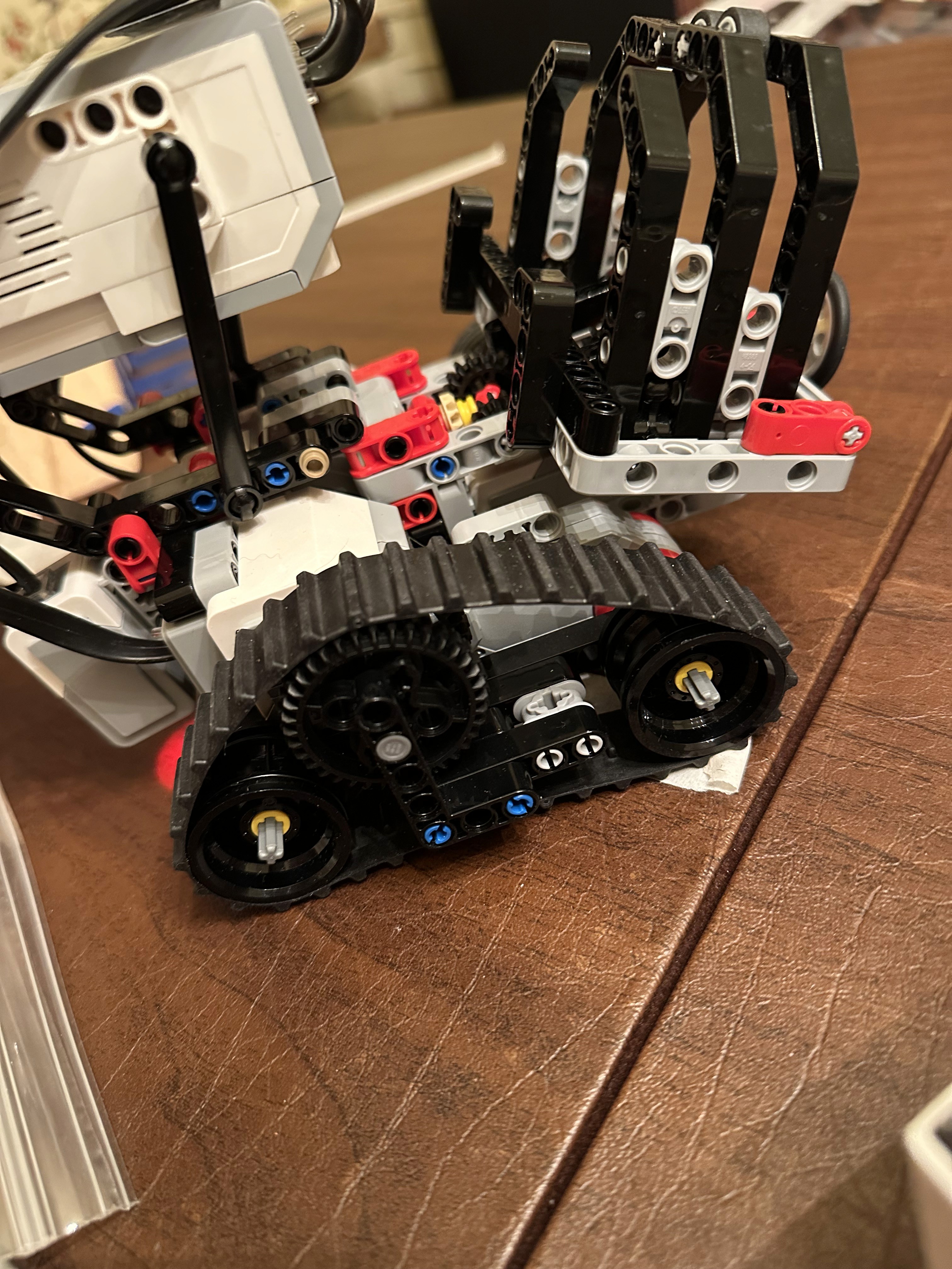
I also added a gear train to the driving base to add more torque. A small drive gear is attached to the motor to help the wheel attached to the larger output gear achieve greater torque.

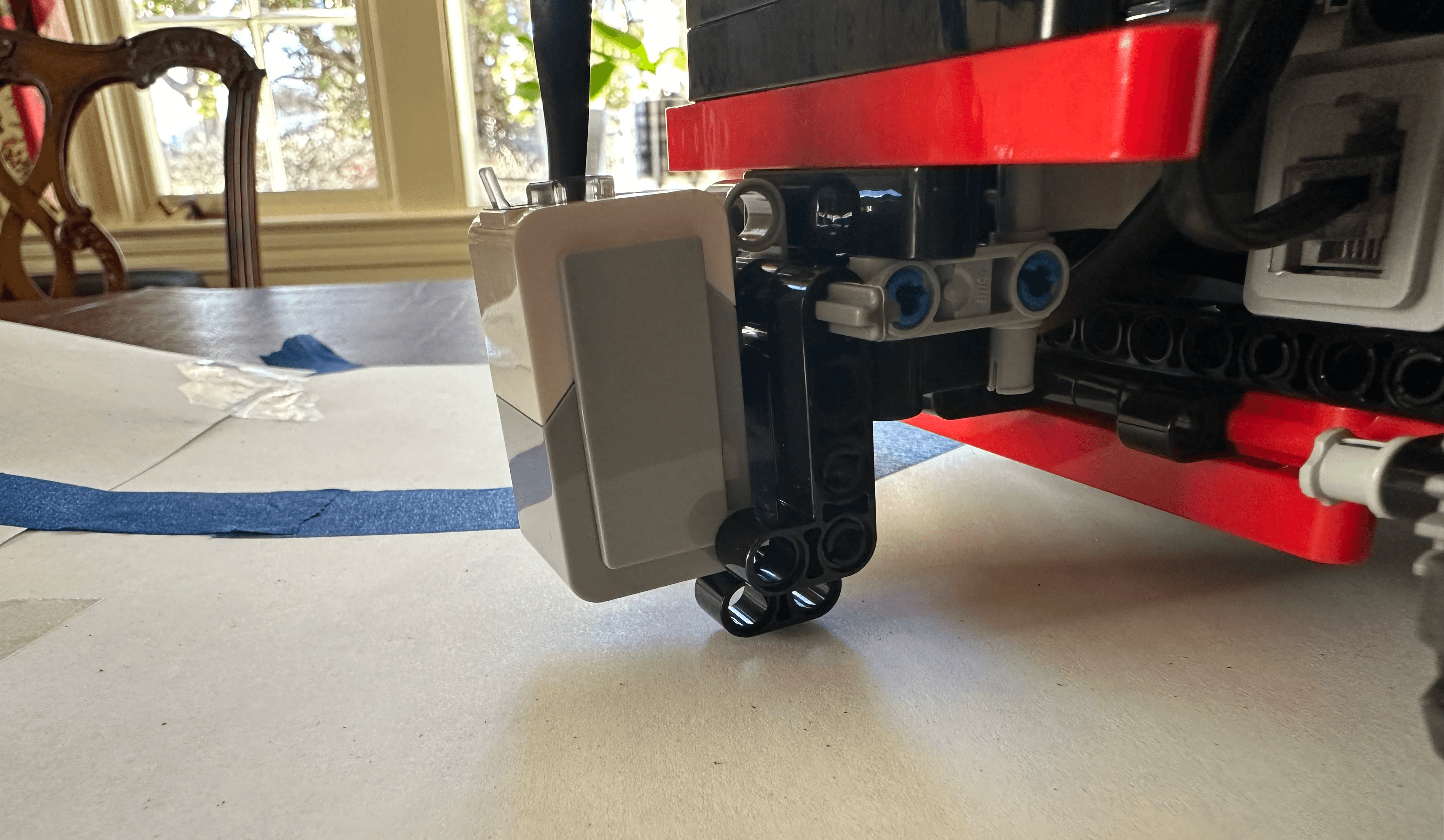
A small L-shaped beam was added just below the color sensor to ensure that the color sensor would never fully flatten against the ground and lose sight of the line

Extra bushings and beam supports were added to the robot's drive base to prevent the axles from bending under the robot's weight. This helps to prevent parts from breaking or falling off and improves the accuracy of the robot's turns.
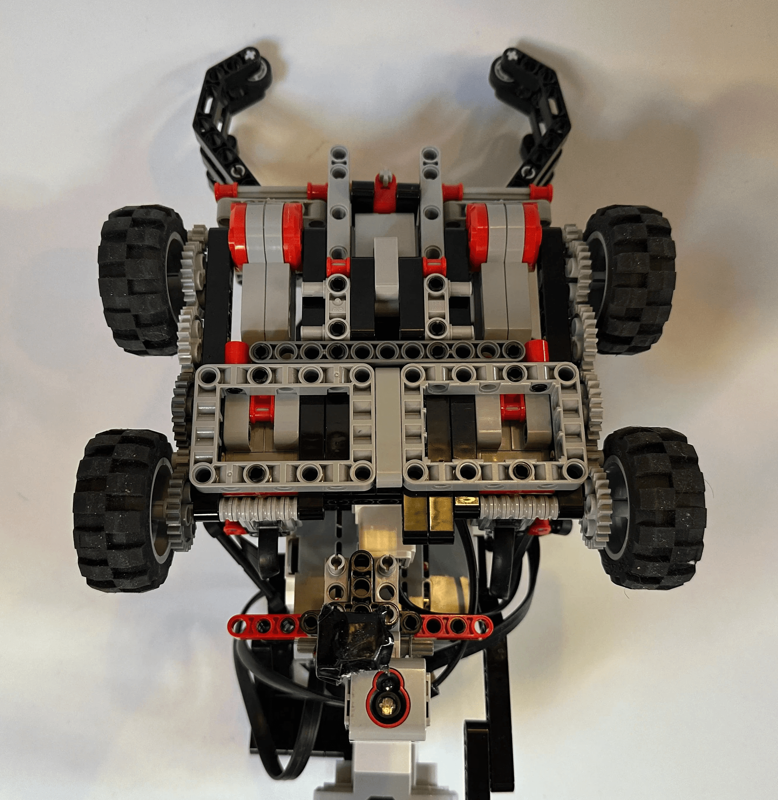
Other Views